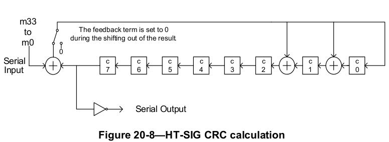
The HT-SIG field of 802.11n PLCP preamble contains a 8-bit CRC for the receiver to validate the sanity of the header. Here is how to calculate it.

HT-SIG contains 48 bits and spans in 2 OFDM symbols (BPSK modulated, 1/2 rate). This diagram from the 802.11-2012 standard describes the logic to calculate the CRC for the first 34 bits of the field.
Here is a Python version of the implementation.
1 2 3 4 5 6 7 8 9 10 11 12 13 14 15 16 | def calc_crc(bits):
c = [1] * 8
for b in bits:
next_c = [0] * 8
next_c[0] = b ^ c[7]
next_c[1] = b ^ c[7] ^ c[0]
next_c[2] = b ^ c[7] ^ c[1]
next_c[3] = c[2]
next_c[4] = c[3]
next_c[5] = c[4]
next_c[6] = c[5]
next_c[7] = c[6]
c = next_c
return [1-b for b in c[::-1]]
|
c is the 8-bit shift register. For each incoming bits, we calculate the next value of each bit in the register and store them in next_c.
Finally, we perform two operations: reverse and two's complement. Note that c[7] is the first output bit.
The standard also provides a test case.
1 2 3 4 | >>> s = '1 1 1 1 0 0 0 1 0 0 1 0 0 1 1 0 0 0 0 0 0 0 0 0 1 1 1 0 0 0 0 0 0 0'
>>> bits = [int(b) for b in s.split()]
>>> calc_crc(bits)
[1, 0, 1, 0, 1, 0, 0, 0]
|
Translating the logic into HDLs such as Verilog is quite straightforward.
1 2 3 4 5 6 7 8 9 10 11 12 13 14 15 16 17 18 19 20 21 22 23 24 25 26 27 28 29 30 31 32 33 34 35 | module ht_sig_crc (
input clock,
input enable,
input reset,
input bit,
input input_strobe,
output [7:0] crc
);
reg [7:0] C;
genvar i;
generate
for (i = 0; i < 8; i=i+1) begin: reverse
assign crc[i] = ~C[7-i];
end
endgenerate
always @(posedge clock) begin
if (reset) begin
C <= 8'hff;
end else if (enable) begin
if (input_strobe) begin
C[0] <= bit ^ C[7];
C[1] <= bit ^ C[7] ^ C[0];
C[2] <= bit ^ C[7] ^ C[1];
C[7:3] <= C[6:2];
end
end
end
endmodule
|
Here we use the generate block to do the bit-reverse and negation.